Terpopuler 29+ PWM Inverter Schematic
Poin pembahasan Terpopuler 29+ PWM Inverter Schematic adalah :

Electronic Guide Sumber electronicguideandmore.blogspot.com

PWM Inverter Circuit Sumber www.theorycircuit.com

PULSE WIDTH MODULATED INVERTER Sumber www.ewh.ieee.org

Inverter 5000W with PWM Pulse Width Modulator Sumber rangkaianlo.blogspot.com

Inverter Circuit Page Power Supply Circuits Next Gr Sumber wiringd.com

IC TL494 PWM Modified Sine Wave Inverter Circuit Sumber makingcircuits.com

1500 watt PWM Sinewave Inverter Circuit Homemade Circuit Sumber www.homemade-circuits.com

sinewave inverter circuit SG3524 PWM SL technological Sumber sltech360.blogspot.com

Schematic structure of a voltage PWM inverter Download Sumber www.researchgate.net

shows the complete circuit diagram of the PWM inverter Sumber www.researchgate.net

Simple PWM inverter circuit diagram using PWM chip SG3524 Sumber circuitsgallery.blogspot.com

PWM inverter circuit 500 Watt low cost Circuits DIY Sumber www.circuitsdiy.com

Build a 250 to 5000 watts PWM DC AC 220V Power Inverter Sumber streampowers.blogspot.com

PWM Sinewave 5kva Inverter Circuit Sumber www.homemade-circuits.com

250W 5000W SG3524 DC AC Inverter Circuit Electronics Sumber 320volt.com
pwm inverter schematic diagram, sg3524 pure sine wave inverter circuit, pengertian pwm inverter, inverter tl494 schematic, ic pwm inverter, sg3524 inverter circuit, skema inverter pwm, rangkaian inverter sg3525,
Electronic Guide Sumber electronicguideandmore.blogspot.com
PWM Inverter ElectroSchematics com
In order to increase the efficiency of the PWM inverter the electronic circuit is highly sophisticated with battery charge sensor AC mains sensor Soft start facility output control etc The PWM controller circuit uses PWM IC KA 3225 or LM 494 These ICs have internal circuits for the entire operation of the pulse width modulation
PWM Inverter Circuit Sumber www.theorycircuit.com
PWM Inverter Circuit Theorycircuit
16 04 2020 PWM Pulse Width Modulation signal based inverters are produce output as pure sine wave and it can be used for any electric appliance that meets the inverter output range Simple and powerful PWM inverter circuit diagram designed with IC SG3524 Regulating Pulse Width Modulator gives upto 230V AC from 12V DC supply PWM Inverter Circuit diagram
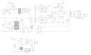
PULSE WIDTH MODULATED INVERTER Sumber www.ewh.ieee.org
250 to 5000 Watts PWM DC AC 220V Power Inverter
250 to 5000 Watts PWM DC AC 220V Power Inverter This is a heavy duty design of a Pulse Width Modulator DC AC inverter using the chip SG3524 I ve been using it as a backup to power up all my house when outages occur since aprox 6 years non stop If you like the work and intend to build the c
Inverter 5000W with PWM Pulse Width Modulator Sumber rangkaianlo.blogspot.com
800VA Pure Sine Wave Inverter s Reference Design Rev A
800VA Pure Sine Wave Inverter s Reference Design 2 1 1 Inverter Mode The method in which the low voltage DC power is inverted is completed in two steps The first step is the conversion of the low voltage DC power to a high voltage DC source and the second step is the conversion of the high DC source to an AC waveform using pulse width
Inverter Circuit Page Power Supply Circuits Next Gr Sumber wiringd.com
PWM Pulse Width Modulation for DC Motor Speed and LED
Pulse Width Modulation PWM allows for electronic control over DC motor speed or LED brightness This articles features schematics and photos of circuits for making PWM without a microcontroller but instead uses a 74AC14 logic inverter chip diodes a capacitor and potentiometer
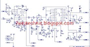
IC TL494 PWM Modified Sine Wave Inverter Circuit Sumber makingcircuits.com
3 Phase PWM Power Inverter Circuit
28 11 2020 The proposed 1500 watt PWM sinewave inverter is designed using extremely basic concept through a couple of IC 4017 and a s single IC 555 then sir please do you have a 50AMP battery charge controler schematic for the solar thanks and i will be looking forward to hearing from you
1500 watt PWM Sinewave Inverter Circuit Homemade Circuit Sumber www.homemade-circuits.com
1500 watt PWM Sinewave Inverter Circuit Homemade Circuit
250W PWM inverter circuit SG3524 A 250W PWM inverter circuit built around IC SG3524 is shown here SG3524 is an integrated switching regulator circuit that has all essential circuitry required for making a switching regulator in single ended or push pull mode
sinewave inverter circuit SG3524 PWM SL technological Sumber sltech360.blogspot.com
PWM inverter circuit based on SG3524 12V input 220V
06 08 2008 PWM or Pulse width Modulation is used to keep the output voltage of the inverter at the rated voltage 110V AC 220V AC depending on the country irrespective of the output load In a conventional inverter the output voltage changes according to the changes in the load To nullify effect caused by the changing loads the PWM inverter correct the
Schematic structure of a voltage PWM inverter Download Sumber www.researchgate.net
Introduction to PWM Inverters Electronic Circuits and
transformer The inverted signal itself is composed of a pulse width modulated PWM signal which encodes a sine wave The duty cycle of the output is changed such that the power transmitted is exactly that of a sine wave This output can be used as is or alternatively can be filtered easily into a
shows the complete circuit diagram of the PWM inverter Sumber www.researchgate.net
PWM Techniques A Pure Sine Wave Inverter

Simple PWM inverter circuit diagram using PWM chip SG3524 Sumber circuitsgallery.blogspot.com
PWM inverter circuit 500 Watt low cost Circuits DIY Sumber www.circuitsdiy.com
Build a 250 to 5000 watts PWM DC AC 220V Power Inverter Sumber streampowers.blogspot.com
PWM Sinewave 5kva Inverter Circuit Sumber www.homemade-circuits.com
250W 5000W SG3524 DC AC Inverter Circuit Electronics Sumber 320volt.com


0 Komentar